When an original memory component becomes obsolete, unavailable, or difficult to source, finding a reliable replacement memory solution is critical to keeping your production lines moving without costly delays. However, selecting the right alternative requires strict attention to engineering details to prevent system failures. In this guide, we will walk you through the essential specifications you need to evaluate when choosing a replacement memory chip, ensuring seamless compatibility and optimal performance for your hardware designs.

What Is a Replacement Memory Chip?
A replacement memory chip is an alternative memory IC selected to substitute an unprocurable, obsolete, or cost-prohibitive original memory device while preserving the system’s functional behavior, timing integrity, and communication protocols.
Here are two common replacement alternatives:
- Drop-in Replacement: A drop-in replacement matches the original component identically in form, fit, and function. It shares the exact same pinout, package dimensions, timing parameters, and electrical characteristics. You can solder this chip directly onto your existing PCB design without modifying the hardware layout or writing new firmware.
- Functional Replacement: A functional replacement provides the required memory function but does not necessarily have an identical physical or electrical implementation. It may require PCB modifications, changes to firmware, updated timing settings, or additional system-level validation.
Key Specifications for a Replacement Memory Chip
Below are the critical parameters that must be evaluated.
1. Memory Type
The fundamental architecture of the alternative must match your system design. When evaluating a RAM alternative, substituting within volatile memory requires matching SRAM, SDRAM, DDR3, DDR4, or LPDDR architectures. For non-volatile storage, distinguish between byte-addressable EEPROM, execute-in-place (XIP) NOR Flash, and block-based NAND Flash (SLC, MLC, TLC).
2. Memory Capacity
Device density must fulfill memory mapping requirements. Verify not only the total density (e.g., 64 Mbit vs. 128 Mbit) but also the internal organization and bus width (e.g., 8M x 8-bit versus 4M x 16-bit). In situations where a higher-density component serves as a temporary substitute, verify that extra high-order address pins are either tied appropriately to ground/VCC or supported by the memory controller’s addressing registers.
3. Interface and Protocol
How the component physically and logically communicates with the host processor is non-negotiable. For non-volatile flash storage, determine whether your system architecture utilizes a serial interface (such as standard SPI, I2C, dual SPI, or Quad SPI) or a parallel interface. For dynamic RAM, ensure the specific signaling standard (such as SSTL, HSTL, or LVCMOS) aligns perfectly. A mismatch in communication protocols or signaling standards guarantees complete functional failure of the subsystem.
4. Operating Voltage
Electrical compatibility is fundamental to both the immediate functionality and the long-term reliability of the system. You must verify both the core operating voltage (VCC/VDD) and the input/output voltage (VCCQ/VDDQ). Modern, low-power revisions of silicon might operate exclusively at 1.2V, whereas older legacy components in the same family might require 1.5V, 1.8V, or even 3.3V. Supplying excessive voltage to a modern replacement part will cause immediate thermal damage and silicon degradation, while insufficient voltage will lead to unpredictable logic errors and failure to initialize.
5. Speed and Timing
The clock frequency and internal latency parameters must meet or exceed the original system specifications. Critical timing metrics—such as CAS latency (tCAS), Row Address to Column Address Delay (tRCD), and Row Precharge Time (tRP)—dictate how fast the system can read and write data. If your original system operates at 3200 MT/s, your replacement must reliably support at least that speed. While a faster memory chip can usually downclock safely to match a slower system bus, installing a slower chip will bottleneck your processor, throttle your system, or cause outright boot failures.
6. Package and Pin Configuration
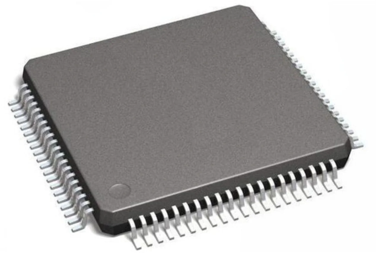
For a successful drop-in replacement, the physical footprint is critical. Common surface-mount packages like BGA (Ball Grid Array), TSOP (Thin Small Outline Package), WSON, and SOIC must match exactly. Compare the mechanical outline drawings in both datasheets to verify pin spacing (pitch), overall component height, and physical dimensions. Most importantly, verify the pin assignments. Even if two candidate chips utilize an identical 96-ball BGA package, the internal trace routing (pinout) can differ significantly between different silicon manufacturers, leading to short circuits if installed blindly.
7. Temperature and Reliability Requirements
The operating environment should also be considered. Check the required temperature range and any application-specific reliability requirements. A replacement intended for industrial, automotive, medical, or other demanding applications may need to meet temperature and reliability requirements beyond those of a standard commercial component.

How to Verify Memory Chip Compatibility
Before replacing, use the following verification process:
- Find the original part number: Read the complete marking from the component or BOM, noting critical parameters like temperature grade, silicon revision, or packaging tape format.
- Download the original datasheet: Secure the official manufacturer datasheet, paying close attention to published errata, revision notices, and package thermal resistance data.
- Record key specifications: Create a comparison list covering memory type, capacity, interface, voltage, speed, timing, package, pin configuration, and temperature range.
- Compare candidate replacement parts: Cross-evaluate candidate components against the baseline metrics to detect functional, timing, or logical deviations.
- Check electrical and pin compatibility: Confirm supply requirements, I/O levels, signal assignments, bus width, and timing.
- Confirm package and dimensions: Verify the package, pin or ball count, footprint, body size, and height.
- Review availability and lifecycle status: Confirm that the chosen alternative is in active production with healthy factory availability.
- Test the replacement in the target application: Mount candidate samples on functional test boards and conduct rigorous functional validation.
How to Find the Right Replacement Memory Chip
Once the technical requirements are defined, sourcing from a reliable memory chip supplier becomes the next challenge. A suitable replacement must not only meet the required specifications but also be available in the required quantity and condition.
At Mayhwa, we provide global sourcing and supply chain services for electronic component buyers. Our role is to help customers identify suitable component options based on their requirements and sourcing conditions. We maintain inventory across our Shenzhen and Hong Kong warehouses and work with a global supplier network to support urgent RFQs and shortage situations.
We also support small-batch purchasing without MOQ restrictions and unsealed retail requirements. All products are described by Mayhwa as fully traceable and subject to rigorous testing with precision equipment.
For a replacement requirement, providing the original part number, datasheet, required quantity, target application, and any known electrical or mechanical constraints can make the sourcing process more precise. From there, candidate alternatives can be evaluated against the original specifications before samples or production quantities are considered.
If you are struggling with EOL notices or volatile supply chains, Mayhwa is here to assist. Contact us with your original part number or sourcing requirements to discuss available options.